You can view and modify architecture diagrams using the diagram editor.

Diagrams are only created by you, and do not change unless you edit them. The violations displayed on the diagram will generally change as the code that maps to the diagrams changes, but the diagram itself remains unchanged. (This is in contrast to e.g. the LSM which is re-"levelized" when the code changes).
You can create any number of diagrams. To add a new diagram, click on the button ![]() above the diagrams list.
above the diagrams list.
Editor toolbar
The Viewing options menu above the editor pane provides alternatives for how the diagram is displayed, such as whether to display cell names or patterns, and whether/when to show violations, dependencies, icons and overrides.

To the left of the Viewing options menu are a buttons that you can use to add a cell, cut a cell, collapse cells, undo/redo edits, and export the diagram (file or clipboard).
Editing operations
Edit operations are available from the toolbar, mouse actions (drag & drop, expand/collapse), and the context menu (right-click).
There are a number of ways to add cells to a diagram:
- Append cell
 (toolbar or context menu) adds a new cell (with empty name and pattern) to the bottom of the diagram (from where it can be moved to the desired location).
 - Drag & drop an item from the associated items list or the dependency breakout. This creates a new cell who's pattern matches the item you dropped.
- Drag & drop a diagram or cells onto the diagram in the diagrams list. This causes the dropped cells to be appended to the bottom of the target diagram (from where they can be moved to the desired location).
- Physically Expand a cell by clicking on the "*" on the top right of the cell (or clicking "physically expand" on the context menu). Where the selected item corresponds to a single container in the model, this adds cells for the contained items.
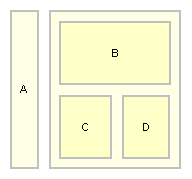
- Wrap (from context menu) a number of cells. This creates a new cell with no name or pattern that encloses the selected cells. A cell that has no pattern will never be directly associated with any actual items in the code-base. As a leaf item, such a cell is meaningless. However, there are many cases where such cells can be extremely useful to group child cells. For example, in the diagram below, there are 4 concrete cells (A, B, C and D) plus a wrapper cell (with no name or pattern). Importantly, it would not be possible to achieve the layering represented by this diagram without the wrapper cell.

Once you have a cell in your diagram, use drag & drop to change its position in the layering and/or to nest it in a new parent cell. You can unwrap (from context menu) cells that enclose child cells. To edit the name or pattern of a cell, select it and edit the relevant fields in the properties viewer.
When you get Structure101 Studio to automatically initialize a diagram for you, it will "levelize" the items according to the current dependencies - cells will be arranged so as to minimize the number of feedback (upward) dependencies. Often this is pretty close to the desired layering, but you can easily adjust the "suggested" layering. If at any time you wish to use Structure101's levelizing algorithm again you can "relevelize" from the context menu.
Overrides
A diagram defines layering through the top-down arrangement of cells. In general, cells may only be used by cells in higher layers (i.e. all dependencies point down).
An override is used to define an exception to this rule:
- An "allows" override (shown green) indicates that a cell can use some other cell higher in the layering, or can use a cell below the next layer when "strict layering" is applied:

- A "disallows" override (shown red) indicates that a cell is not allowed to use some other cell, even though it is lower in the layering.

To define an override, move the mouse over the "from" cell, right-click and select "Create override" and then left-click on the "to" cell to complete the operation.
To allow an existing violation, you also have the option of right-clicking the violation and selecting "Derive override".